Welding Symbols
Welding symbols are a set of information conveyed by the design department to the welding Engineer and the welding operator. It contains all the necessary information viz. welding position, dimensions and geometry of the weld, details of groove/fillet, welding process, etc.
A basic weld symbol consists of three parts namely;
- Arrow Line
- Reference Line
- Tail
These are shown in the diagram given below
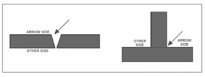
Arrow Line: Arrow indicates the position of the joint. The arrow points to one side of the joint. This is called the ARROW SIDE and the side other than the arrow side is called the OTHER SIDE.
The arrow side and other side is shown in the diagram given below;
Reference Line: Most of the Details about the weld are given on the reference line such as the shape of the groove or the fillet, Geometry, and dimensions of the weld, etc. In the ISO system, a weld on the arrow side is indicated by placing the weld symbol above the solid reference line and a weld on the other side is shown below a dashed line, as shown in the figure given below;
Whereas in the AWS system the weld symbol for a weld is placed below the reference line and for a weld on the other side is shown above the line as shown in the figure given below; (NOTE: Dashed line is not used in AWS system).
In the ISO system symbols on the solid line always refer to the arrow side of the joint and symbols on the dashed line indicate a weld on the other side. The dashed line can be drawn either above or below the solid line but as per standard practice, the dashed line is placed below the solid reference line.
To bring more clarity about the arrow side and the other side in a fillet joint, please see the diagram given below;
NOTE: If the weld is made on both sides, as in a double fillet weld (or double groove), the dashed line can be omitted since the weld symbol is placed on both sides of the reference line or lines. Please see the diagram given below;
Tail: The third important part of a welding symbol is tail, Tail is used to designate additional information viz. Reference code and (or) welding process to be used. The tail may be omitted if not required.
ELEMENTARY SYMBOLS
In addition to the basic parts of a welding symbol i.e. Arrow line, Reference line, and the tail certain elementary symbols are provided on the reference line. The elementary symbols may be complemented by Supplementary symbols, Dimensions, and Complementary information.
The elementary symbols are given below;
Also read: Welding Positions
Also read: Welding Defects
Also read: How to write a welding procedure specification (WPS)
Also read: Thickness range for the welder qualification test
Also read: P-number, F-number, and A-number in welding


![Saudi Aracmo GI 7.028 (SA-9466) Mobile Crane Operator Daily Inspection Checklist -2022 [PDF]](https://blogger.googleusercontent.com/img/b/R29vZ2xl/AVvXsEjjqlj8kIuErWV-fogjqZWkEjkXJW1cUjZgxYuYDzZrePGV1IR53ShWP2cfij4S5DbquaoCZmVrI4HXLPS3J1D0Uo3KQ8EcOKJGNLJ0jt4jQQm7WBQY9EMjTEmmqpHaU2_U7cKrJOJgMOInJiMy-MHQOqO6AuqEsJXy3e4nxenuKKf57H8mwyz3kUXgafU/s72-c/dsdsdsdsds_001-qcskills-7.028.jpg)
No comments:
Post a Comment